| A | 8-bit accumulator |
| HL | 16-bit accumulator and address register, can be used as separate 8-bit registers H, L |
| DE | 16-bit data register, can be used as separate 8-bit registers D, E |
| BC | 16-bit data register, can be used as separate 8-bit registers B, C |
| IX | 16-bit address register |
| IY | 16-bit address register |
| C test |
as subtraction |
unsigned numbers "else jump" |
signed numbers "else jump" |
| if (a >= b) |
if (a-b >= 0) |
JP C or JR C |
JP PO |
| if (a < b) |
if (a-b < 0) |
JP NC or JR NC |
JP PE |
| if (a == b) |
if (a-b == 0) |
cascaded JP NZ or JR NZ |
cascaded JP NZ or JR NZ |
Ken Shirriff wrote Reverse-engineering
the division microcode in the Intel 8086 processor. Again
Intel engineers opted for unsigned division as core and signed
division as unsigned division with pre and post steps. This
approach has one little disadvantage: -32768 is no valid quotient
for the 32-bit by 16-bit signed division of the 8086.
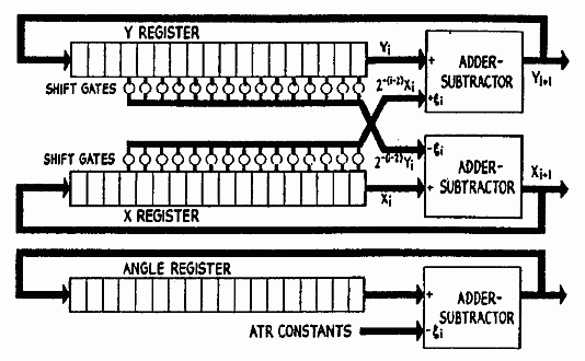
 The new Y value
is the current Y value plus (if angle is positive) or minus (if
angle is negative) the shifted current X value.
The new Y value
is the current Y value plus (if angle is positive) or minus (if
angle is negative) the shifted current X value. The new X value is the
current X value minus (if angle is positive) or plus (if angle is
negative) the shifted current Y value.
The new X value is the
current X value minus (if angle is positive) or plus (if angle is
negative) the shifted current Y value. And the new angle θ
value is the current angle θ value minus (if angle is positive) or
plus (if angle is negative) an ATR constant.
And the new angle θ
value is the current angle θ value minus (if angle is positive) or
plus (if angle is negative) an ATR constant.