@author Andre Adrian, DL1ADR
@date 17jan2015
Ruhmkorff coil or Tesla coil experiments are fun. High voltage
sparks and Geissler
tubes electrical glow discharge create some "Frankenstein
laboratory" feeling. As teenager the author experimented with car
ignition coils and electromagnetic interrupters. The television
set with a vacuum picture tube uses an electronic device instead
of a mechanical interrupter to produce high voltage. The active
device in the flyback converter in the TV was first a vacuum tube,
later a transistor. A very simple flyback converter design is the
Slayer exciter. It was (probably) published by Dr. Ronald R.
Stiffler, WA7RTQ. This simple circuit allows to build a tiny high
voltage generator. The generator does produce alternate current in
the radio frequency range of typical some hundreds kilohertz (some
100000 cycles per seconds).
Some people attribute "extraordinary" abilities to the simple
exciter circuits of Dr. Stiffler and others. The author does not
believe in "perpetual
motion" engines, engines that have a efficiency above 100%.
The "Panacea-BOCAF On-Line
University" is a little cautious, too. At least they write:
"SEC Exciters (Do Not) create energy".
Günter Wahl, the author of the german book "Experimente
mit Tesla Energie" wrote wisely: "wobei der Fantasie des
Lesers die Interpretation überlassen bleibt, ob die
Energie-Übertragung mit Teslawellen, Skalarwellen oder einfach nur
mit leitungsgebundener Hochfrequenz stattfindet [the
interpretation is left to the
reader's imagination,
whether the energy transfer takes place with
Tesla waves,
scalar waves or just
over wired high-frequency]".
The author wonders sometimes about the progress physics makes.
Some ten years ago there was still strong believe in the "aether",
a mystical substance that is the transport medium for
electromagnetic waves. Maxwell and others did prove that
electromagnetic waves can propagate through vacuum and do not need
an "aether". Today physicists are talking about "black matter".
Again some mystical substance that you can not experiment with,
but is needed to make some theories work. Today we know that the
"aether" theory was wrong, but not the practical work of the
experimenters. The author does not know if the "black matter"
theory will be proved wrong, too. But at all times the scientists
were 99.99% sure that they know nearly everything and that nothing
interesting was left in the still unknown. But they were proven
wrong again and again. Electrical super conduction or superconductivity
at liquid nitrogen temperature of 77 Kelvin (−195.79 °C) was
though impossible by the physicists one generation ago. The same
is true for the giant
magneto-resistance effect that gives us today magnetic
hard-disk storage in the Tera bytes range.
The author likes simple experiments that make a "wow" effect. The
pop-pop boat
with the pulsed jet engine is a good example. The one vacuum
tube radio receiver is another.
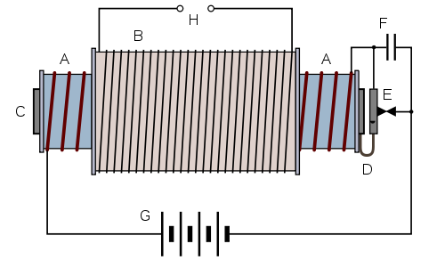
Let's start with the Ruhmkorff
coil from Heinrich Daniel Rühmkorff. The battery G provides
direct current (DC) voltage. The primary winding A and the
magnetic core C work as an electro magnet. The iron armature E
carries an opener contact. The spring D brings the iron armature
back in default position if no magnetic field pulls it away. The
interrupter E operates the electro magnet in an on-off manner. The
spring D closes the contact E and current can flow into the
magnet. As the magnetic field builds up, the magnetic core C pulls
the iron armature (left part of E) and the electrical circuit is
interrupted. The magnetic field collapses and the iron armature
moves again to the original position. The cycle starts again. The
capacitor F improves the life time of the interrupter. Every time
the magnetic field collapses, a (relative) high voltage is induced
into the primary winding. This induction voltage causes a little
spark at E. The spark does remove material from the interrupter
contact. The capacitor F has no electrical change at the moment E
opens. The induction voltage does charge the capacitor. After
contact E closes again, capacitor F gets discharged. The capacitor
F operates as an EMI/RFI (electro magnetic interference/radio
frequency interference) suppression capacitor. This capacitor
influences the Ruhmkorff coil radio frequency and the peak
secondary voltage at H. Less capacitance of F gives a higher
secondary voltage but more EMI/RFI, too.
Because the magnetic field changes between zero and some maximal
value, a voltage is induced into the secondary winding H. The
secondary winding has much more turns than the primary winding.
The Ruhmkorff coil works as a step-up transformer.
Picture: Ruhmkorff coil (from
Wikipedia article)
The Tesla coil high voltage generator is nothing special. It is
an ignition coil design. To improve the transfer of electrical
power from primary coil to secondary coil both coils are made
resonant to each other. Both coils oscillate at the same
frequency. The secondary coil of a Tesla (resonance) transformer
has often a "top" capacitor in the shape of a sphere or a torus.
The inductance and the capacitor form a resonance circuit. The
primary coil has the EMI/RFI suppression capacitor to complete a
resonance circuit. Without explicit capacities at primary and
secondary coils there are still the parasitic capacitances of the
coils themselves. Between two adjacent wires in the winding there
is a little voltage difference because of the resistance of the
coil wire. A capacitor consists of two isolated conductors that
have a voltage difference. Therefore every practical inductance
has some parasitic capacitance.
The inductances of a Tesla transformer are given, as is the
capacitance of the top capacitor. Therefore the capacitor at the
primary coil is used to bring the Tesla transformer to resonance.
Because both resonant circuits influence each other, both can not
oscillate at the same frequency. The resonant circuits form a band
pass. One resonant circuit oscillates at a lower frequency, the
other at a higher frequency. A loose coupling gives a small
difference between the two frequencies, a tight coupling gives a
larger difference.
The traditional method to find the "optimum" setting is to measure
the resonance frequency of the secondary resonant circuit. The
primary coil is far away and does not influence this measurement.
In the second step the primary resoant circuit is "tuned" to the
same resonant frequency, again without influence from the other
resonant circuit. In the third step the coupling factor between
both circuits is optimized. Normally the primary coil is located
at the base of the secondary coil. For looser coupling the primary
coil is moved further away (further down) from the base. To allow
this, the secondary winding does not start at the bottom of the
secondary coil carrying structure, like an isolator material tube,
but a little further up. The length of the high voltage spark is
normally the criterion for optimality. But sometimes the
capabilities of the interrupter, like the transistor temperature,
or the capabilities of the power supply determine the optimum
setting.
The solid state flyback converter or "Slayer Exciter" replaces
the relay coil and relay opener contact with a solid-state device,
a transistor. Transistor is short for transfer resistor,
an electronic device that changes the resistance value between
connectors emitter and collector depending on the current between
base and emitter. In the "Slayer Exciter" flyback voltage inverter
circuit the transistor switches fast between the minimum
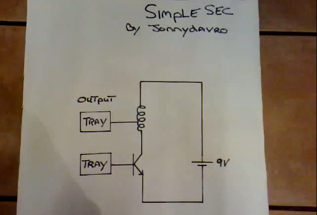
resistance and maximum resistance state. The following circuit was
published by "Ludic Science" at Youtube. The green LED can be
replaced by two 1N4148 diodes in series connection.
The flyback converter is an oscillator. As any oscillator it needs
a positive feedback from output of the amplifier to input of
amplifier. The "Slayer Exciter" uses a clever (brilliant) feedback
solution. After closing the switch, current can flow through the
22kΩ resistor, the base to emitter path within the transistor back
to the battery. The base to emitter current brings the transistor
into "minimum resistance" state. A (large) current can flow from
the battery through the primary coil with 3 turns, the collector
to emitter path within the transistor back to the battery. The
difference in current creates a changing magnetic field in the
primary coil which creates a changing magnetic field in the
secondary coil which again creates a changing voltage in the
secondary coil. The top connector of the secondary coil has no
connection. This is not true. The electro magnetic field closed
the circuit. There is an "invisible" load resistor between the top
connector of the secondary coil and the negative pole of the
battery. A current can flow through the secondary coil, the load
resistor and the LED diode. The forward voltage of a green LED is
between 1.5 volts and 2 volts. Because the LED cathode is
connected to ground (the negative pole of the battery), the anode
voltage of a conducting LED is -1.5 volts. Such a negative voltage
does switch the transistor into "maximum resistance" state. The
current through the "feed" resistor 22k still tries to switch the
transistor "on", but the influence of the negative voltage at the
LED cathode is stronger. The combined effect (sum of the currents
into the base of the transistor) switches the transistor "off".
The current through primary coil decreases, the magnetic field
collapses, after a short time there is no more voltage at the
secondary coil and no more "inhibit" voltage through the LED at
the base. The current through the 22kΩ resistor can switch the
transistor "on" and the cycle starts again. The LED is
anti-parallel to the base-emitter diode of the transistor. The
positive amplitude of the radio frequency high voltage travels
through the transistor, the negative amplitude travels through the
LED. There is no rectification in the secondary circuit (secondary
coil, "invisible" Rload and the anti-parallel diodes). Oscillation
can only happen if there is a time delay between cause and effect.
The cause is the charging of the secondary coil via the primary
coil. The effect is a negative voltage at D1 that switches off the
transistor. Both coils can store magnetic energy. Without a large
enough inductance (storage capacity) of the secondary coil, the
effect negates too fast the cause and the oscillations die away.
The transistor needs a short time (nano seconds) to forward the
"switch off" state from the input to the output. This transition
delay supports the oscillation, too.
Note: A flyback converter is a DC/DC converter. In the case of a
radio frequency high voltage generator the rectifier diode at the
secondary coil is missing. Because of this one can not
differentiate between a flyback or forward converter. The author
used the name flyback converter because a flyback converter is
typically used if high DC output voltage, low output current is
needed.

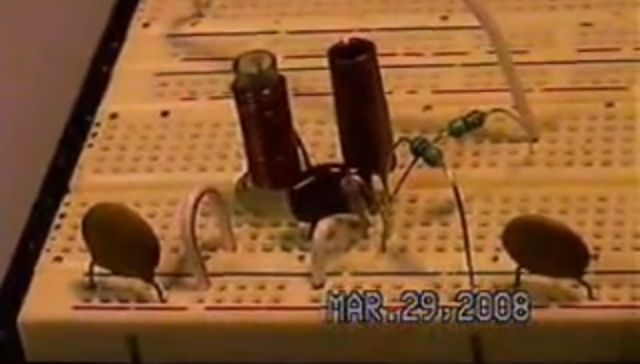
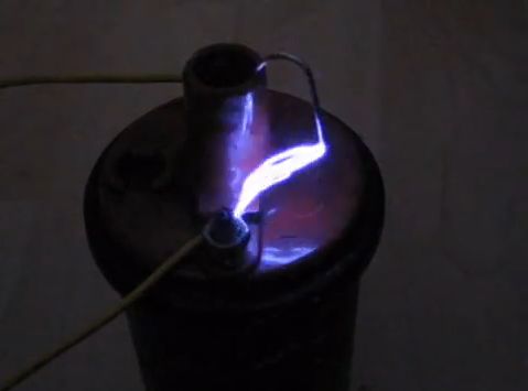
Picture: Transistor Ruhmkorff coil (Ludic Science
Miniature Tesla Coil). Click on picture for Youtube video.
The correct wiring of the transformer is important for the
operation of the high voltage generator. This problem does not
exist with the Ruhmkorff coil or the ignition coil. If the flyback
converter does not oscillate, you have to change the connection of
the primary coil. Put the first connector at the place the second
connector was and vice versa. This changes a negative feedback
into a positive feedback. Another explanation is: The transistor
as an amplifier has a phase shift of 180° between input and
output. The transformer as part of the feedback network has to
provide another 180° phase shift. Correct connection of the
primary coil gives this phase shift, wrong connection gives a
phase shift of 0°.
LTSpice
is a (very good) circuit simulation program from Linear
Technology. Let's see what we can learn about the flyback
converter circuit from simulation. The "Tesla" transformer
consists of a AM radio ferrite rod with primary coil L1 with 6
turns and secondary coil L2 with 275 turns. The inductance of a
coil is AL times the square of the number of windings.
The AL value depends on the magnetic core material in
the transformer. The simulation uses an AL value of
89nH per turn. This gives 3.2μH inductance for the primary coil
and 4.8mH for the secondary. The magnetic coupling between primary
and secondary coil was measured as 0.6. The resistance of the
secondary winding was measured as 10.7Ω. The "invisible" load
resistor is now visible as Rload. The flyback converter does not
oscillate if the value of Rload is too high. The reason is simple.
A large value of Rload allows only a (very) small current through
LED D1 which can not overcome the influence of the "feed" resistor
R1.
The simulated circuit has one more capacitor than the original
circuit. C1 is a filter capacitor. The battery V1 has an internal
resistance of 10Ω. At the time Q1 is switched off (no current
flows through the transistor) the filter capacitor charges from
the battery up to 9V. At the time Q1 is switched on C1 will
discharge through the transistor. Because the internal resistance
of C1 is (much) lower than the battery internal resistance the
filter capacitor reduces the battery voltage fluctuations for the
circuit. The transistor 2N2222 or today PN2222A, MBT2222A, PZT2222A was
announced by Motorola at the 1962 IRE Convention. It is a
modern oldtimer. Central Semiconductor offers a PN2222A
SPICE model.
One has to use some tricks to use SPICE successful. That the
battery has an internal resistance of 10Ω is no trick but
realistic simulation. The first trick is to use the voltage source
V_Iin with a voltage of zero volts to have a convenient component
to measure the battery current. Another trick is to give the
battery voltage a time dependent value. The option startup
in the .tran command tells LTSpice to "ramp up" the supply
voltage from 0V to 9V within the first 20μs of the simulation.
This supply voltage disturbance starts the oscillator. Remember,
"an object does not move until an external force ..." and "an
oscillator does not start oscillating until a disturbance
...".
Picture: LTSpice simulator of Slayer exciter (Transistor
Ruhmkorff coil)
The simulation calculates the maximum output voltage for a turns
ratio of 1:50. If the secondary winding has 275 turns, the primary
winding should have 5.5. The oscillator will not start if the
turns ratio gets too large. In this case add another turn to the
primary winding.
Picture: Slayer exciter simulation diagrams. X-axis is turns ratio. Voutmax is maximum output voltage, voutrms is RMS output voltage, vcmax is Q1 collector voltage, pout is output power in mW and the last diagram shows the efficiency in percent.
The simulation waveform results look realistic. The output of the
flyback converter "oscillator" is a fine sine wave. The transistor
is in the "linear state" while it travels from the "minimum
resistance" to the "maximum resistance" state. Linear state
implies power loss. The "switch is off" state has (theoretically)
no power loss because the current through the switch is zero. The
"switch is on" state has (theoretically) no power loss because the
voltage over the switch is zero. In the linear state neither
current nor voltage are zero and we have power loss. The average
power loss is 624mW. Only the PZT2222A version of the 2N2222A can
handle it. A larger value of R1 reduces the output voltage and the
power loss.
The Dr. Stiffler exciter is the "star" of many Youtube videos of
the "free energy" community. A good conjurer does not want you to
see the trick, he wants you to believe in a miracle. Normally
Dr. Stiffler does not show the schematics of his one
transistor circuits in his Youtube videos. One exception is
the "Hybrid
Exciters - Part#1" video from 2010 on Youtube. The
presented circuit is a modified Meissner oscillator. Every
oscillator needs three major building blocks. A resonance
circuit, an amplifier and a positive feedback. In the Dr.
Stiffler circuit there are several resonance circuits. The
obvious LC-circuit is L1 and C1. More hidden is the LC-Circuit
L2 with the L2 parasitic capacity. The transistor internal
Miller capacity between collector and base creates together
with L1, L2 the third LC-circuit. The amplifier is the base
resistor R1, the npn transistor and the collector coil L2. The
feedback is via magnetic coupling between L2 to L1 and/or
capacitive coupling through the Miller capacity. Capacitor C2
forwards the AC radio frequency to the output but blocks the
battery DC voltage.

The Wien bridge oscillator uses two RC-circuits for the frequency
dependent network. The frequency range of the famous HP200CD
sine wave generator is 5Hz to 600kHz. The HP200CD amplitude
limiter uses a light bulb. A amplitude limiter with two
anti-parallel diodes works, too. The Wien bridge uses the parallel
RC-circuit R1, C1 and the series RC-circuit R2, C2. R1 and R2 are
a tandem (stereo) potentiometer. Different values of C1, C2 are
switched into the circuit. A ten to one variation of R1, R2 gives
a ten to one variation of the output frequency. The Wien bridge
network has an attenuation factor of 3. The amplifier network R3
to R6 has an amplification factor a little above 3. The
anti-parallel diodes D1, D2 are the amplitude limiter. The LM833
op-amp is the European answer to the famous U.S.A. NE5532. Both
are low noise bipolar op-amps that are in production for more then
30 years.
The MC1496 or LM1496 is an ancient integrated circuit for a
double-balanced mixer. ON
semiconductor still produces it in a SOIC-14 package, and Mouser
and others distribute it. Unfortunately there is no schematics
that uses symmetric ports for radio frequency in (RF), local
oscillator in (LO) and intermediate frequency out (IF) in the
application note AN531/D "MC1496 Balanced Modulator". But only
with this (expensive) circuit a Gilbert cell mixer shows the full
potential. The three RF transformers for the mixer are build with
ferrite rings FT50-77 for AM radio and FT50-43 for shortwave
radio. The multiple voltage divider R1, R2, R3 provides +1.1V at
pin 5 for bias, +4V at pins 1, 4 for base voltage of the lower two
transistors of the Gilbert cell and +8V at pins 6,12 for base
voltage of the upper four transistors. These voltages have filter
capacitors C1 and C2. For spurious free IF output the input
voltages at RF and LO should be below 10mV RMS. This is a
difference between diode ring mixers and Gilbert cell mixers. The
diode ring mixer needs a (very) strong LO signal, the Gilbert cell
mixer needs a (very) weak LO signal.
The author of the LM1496
LTSpice model is "Ron H".
Some years ago the SA602 (SA612, NE602, NE612) was used as
mixer/LO by radio amateurs. But this device is no longer in
production.
Picture: LM1496 symmetric double-balanced mixer
The author made his ignition coil high voltage generator
experiments in the late 1970s. At this time he has not heard about
micro computers and was (still) fascinated by "brute force"
electrical experiments like short circuit the plus and minus pole
of a car battery with a wire. Today the author is more refined.
But surely he will build a miniature Tesla coil high voltage
generator. The days of "Frankenstein laboratory" experiments are
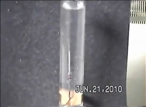
not over. I must repeat the Youtube (pseudo) scientific
experiments with a radio frequency generator and a 1N4148 diode in
a test tube that will produce hydrogen and oxygen bubbles. I am
not in search of free energy or black matter, but I am in search
of fun and a little oxyhydrogen explosion.